Direct-to-Chip Cooling: A Technical Guide
- Share
- publisher
- CoolSpace
- Issue Time
- Oct 19,2026
Summary
Direct-to-chip (D2C) cooling delivers coolant directly to GPU and CPU heat sources through precision cold plates, enabling rack densities of 80-120kW while maintaining chip junction temperatures 20-30°C below air-cooled levels. This technical guide covers the engineering, deployment, and operational considerations.

Direct-to-Chip Cooling: A Technical Guide for High-Density GPU Cluster Deployments
Reading time: 8 min read | Published: October 19, 2026 | Category: Cooling Technology
In this article: Key Takeaways · What Is Direct-to-Chip Cooling · Cold Plate Engineering · System Architecture · Performance Data · Operational Considerations · Explore Further
Key Takeaways
- Direct-to-chip cooling places the heat exchanger directly on the GPU/CPU package, creating the shortest possible thermal path between the heat source and the coolant — reducing thermal resistance by 60–80% compared to air cooling, according to ASHRAE Datacom Series thermal analysis.
- GPU junction temperatures under D2C cooling typically run 20–30°C lower than air-cooled equivalents, enabling sustained boost clock operation and improving computational throughput per watt.
- D2C systems can handle rack power densities of 80–120kW in standard 42U enclosures, compared to the 15–20kW practical limit for air cooling.
- Modern quick-disconnect fittings and drip-free manifold designs have reduced leak risk to rates comparable to other plumbed building systems, as standardized by Open Compute Project advanced cooling specifications.
What Is Direct-to-Chip Cooling?
Direct-to-chip (D2C) cooling is a thermal management approach that brings liquid coolant directly to the semiconductor package — the GPU die, CPU die, or accelerator ASIC — through a precision-machined cold plate mounted on the chip surface. Unlike rear-door heat exchangers (which cool the air after it passes through the server) or immersion cooling (which submerges the entire board in dielectric fluid), D2C targets heat at its source with the highest possible thermal efficiency.
The principle is straightforward: a cold plate with internal microchannels or fin structures is pressed against the chip's heat spreader with thermal interface material (TIM) between them. Coolant — typically deionized water or a water-glycol mixture — flows through the cold plate channels, absorbing heat at rates of 500–1,500W per cold plate depending on flow rate and design. The heated coolant then exits through flexible tubing to a manifold system that routes it to facility-level heat rejection equipment (dry coolers, cooling towers, or heat recovery systems).
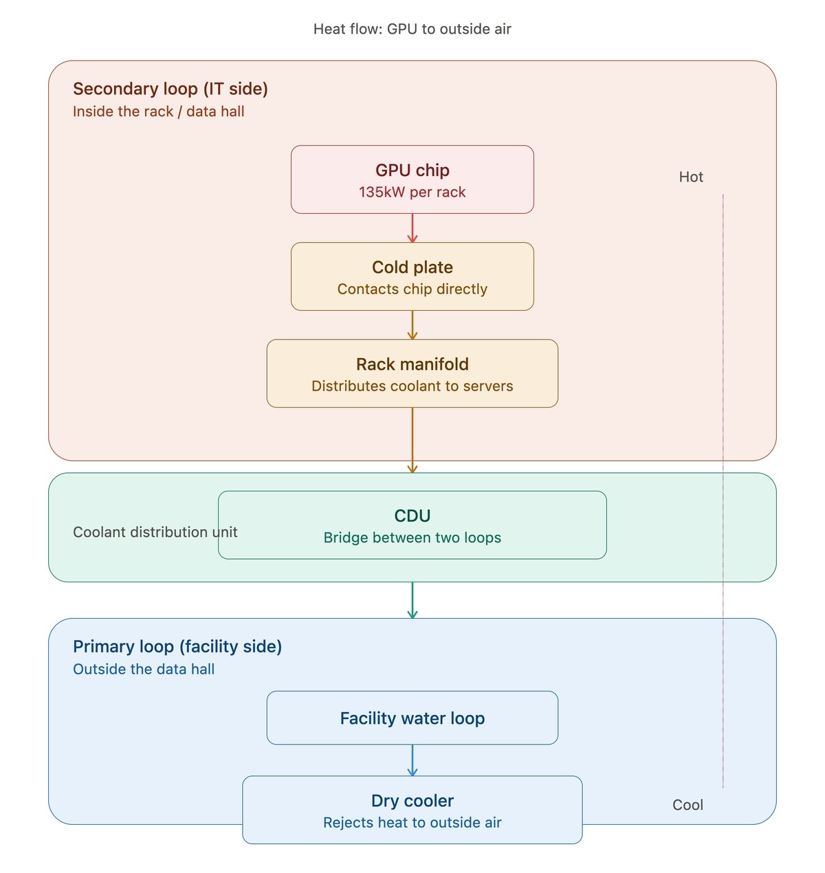
Schematic of a closed-loop direct-to-chip cooling system — coolant flows from facility-level pumps through distribution manifolds to individual server cold plates and returns for heat rejection.
Cold Plate Engineering: Where the Thermal Transfer Happens
The cold plate is the critical component in any D2C system. Its performance determines the thermal resistance between the chip junction and the coolant, which directly governs the maximum power that can be dissipated while maintaining safe operating temperatures.
Microchannel designs use arrays of parallel channels — typically 200–500 μm wide — machined or etched into the cold plate base. These narrow channels increase the surface area in contact with coolant and promote turbulent flow, maximizing heat transfer coefficients. Microchannel cold plates achieve thermal resistances as low as 0.02–0.05 °C/W, meaning a 1,000W chip raises coolant temperature by only 20–50°C at the cold plate interface.
Skived-fin designs use thin metal fins — typically copper — raised from the base plate through a skiving process. This creates a dense fin array with metallurgical continuity between the fins and base, eliminating thermal contact resistance. Skived-fin cold plates offer a favorable balance of thermal performance and manufacturing cost for high-volume production.
Materials selection. Copper provides the highest thermal conductivity (385 W/(m·K)) and is the standard material for high-performance cold plates. Aluminum (205 W/(m·K)) offers a lighter, lower-cost alternative for moderate heat loads. In systems using copper cold plates with aluminum distribution manifolds, corrosion inhibitors in the coolant prevent galvanic corrosion between dissimilar metals.
System Architecture: From Chip to Heat Rejection
A complete D2C cooling system comprises several layers, each engineered for reliability and serviceability:
Server level: Cold plates mounted on each GPU and CPU, connected by flexible tubing to quick-disconnect fittings at the rear of the server chassis. When a server requires maintenance, the quick-disconnects allow the server to be removed from the rack without draining the cooling loop — a critical feature for operational practicality.
Rack level: A vertical manifold pair (supply and return) runs the height of the rack, with branch connections to each server position. The manifold includes isolation valves, flow meters, and temperature sensors for monitoring and diagnostics.
Row level: Rack manifolds connect to row-level distribution headers, which aggregate coolant flow from multiple racks and route it to the facility cooling plant. Balancing valves ensure even flow distribution across racks and rows.
Facility level: Pumping stations, heat exchangers, and heat rejection equipment (dry coolers or cooling towers). Redundant pump configurations (N+1 or 2N) ensure cooling continuity during maintenance. Variable-speed drives on pumps optimize energy consumption to match actual heat load.
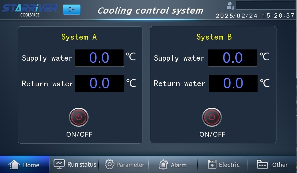
A centralized cooling control system — real-time monitoring of flow rates, temperatures, pressures, and leak detection across every rack and row in the facility.
Performance Data: D2C vs. Air Cooling
Side-by-side comparisons under controlled conditions demonstrate the magnitude of the thermal advantage:
- GPU junction temperature: An NVIDIA H100 operating at 700W TDP shows junction temperatures of 78–85°C under air cooling versus 48–55°C under D2C cooling with 25°C coolant supply — a 30°C reduction, as consistent with NVIDIA data center thermal design guidance.
- Sustained clock frequency: Lower junction temperatures allow GPUs to maintain boost clock frequencies 5–15% above air-cooled sustained rates, directly increasing compute throughput for training and inference workloads.
- Acoustic output: Removing or significantly reducing server fan speeds drops per-server noise from 75–85 dBA (air-cooled) to 50–60 dBA (D2C with reduced fans) or below 40 dBA (D2C with fans eliminated entirely).
- Rack power density: Standard 42U racks support 80–120kW under D2C cooling versus 15–20kW practical maximum for air cooling — a 4–6x increase in compute density per rack position.
Operational Considerations
Leak management. Modern D2C systems use drip-free quick-disconnect fittings that seal automatically when disconnected, preventing coolant release during server removal. Rack-level drip trays and multi-zone leak detection sensors provide defense-in-depth. In well-maintained D2C installations, coolant leak rates are comparable to other plumbed building systems (HVAC, fire suppression).
Coolant management. Water quality must be maintained within specified parameters (pH 7.0–9.0, conductivity below 50 μS/cm for deionized systems, appropriate glycol concentration for freeze protection). Automated monitoring systems sample coolant properties continuously and alert operators when corrective action is needed.
Hot-swappable servers. The quick-disconnect fittings at each server position allow individual servers to be removed and replaced without interrupting cooling to other servers in the rack. This is a non-negotiable requirement for operational data centers and is fully supported by current-generation D2C manifold designs.
Explore Further
CoolSpace integrates direct-to-chip cooling technology into its full range of modular and containerized data center products. Every system is designed for hot-swappable serviceability, closed-loop zero-water-consumption operation, and support for rack densities up to 100kW+.
Explore the CoolBase-1080A/W for AI training clusters or the SR40 V3 Hydro Cooling Container for dense compute applications. Contact the team to discuss your deployment's thermal requirements.
Follow CoolSpace: LinkedIn · News & Updates