Centralized vs. Distributed CDU Architecture: How to Choose
- Share
- Issue Time
- Nov 4,2026
Summary
Compare centralized and distributed CDU architecture for liquid-cooled data centers: failure domains, redundancy, piping, scalability, operations and a practical decision framework for choosing the right layout.
8 min read | High-Density Compute Data Center Infrastructure | Updated November 2026
Executive summary
- Centralized CDU architecture concentrates heat exchange and pumping in a mechanical area and pipes treated coolant to every rack. Distributed architecture puts CDUs at the rack or row, so each unit serves a small local loop.
- Neither approach wins in general. The right choice depends on failure domain, capacity phasing, available space, piping complexity and the operations team that will run the system.
- Many projects settle on a block-based middle path: one redundant CDU group per hall, module or build phase.
If you are designing a liquid-cooled data hall, the coolant distribution unit (CDU) decision shapes more than the equipment list. It determines how large a single failure can become, how you phase capacity, where the piping runs, and how many pumps and filters your operations and maintenance (O&M) team will own for the next decade. This guide compares centralized and distributed CDU architecture on those terms and closes with a decision framework you can apply to your own site. If you need a primer on what happens inside the unit, start with our guide to how a coolant distribution unit works in a liquid-cooled data center.
What centralized and distributed CDU architecture mean
Every CDU does the same job: it isolates the facility (primary) cooling loop from the IT (secondary) loop that carries coolant to the cold plates, and it controls the temperature, flow and pressure of that secondary loop. Architecture is simply a question of where those units live and how many racks each one serves.
Distributed: rack-level and row-level CDUs
A rack-level CDU is mounted in or beside a single rack. A row-level (in-row) CDU sits between racks and serves a row or a group of racks. Facility water is piped to each unit, and each unit manages a short secondary loop. The Open Compute Project's CDU listings include both rack-mounted and in-row units, many built to Google-contributed specifications, with in-row units reaching megawatt-scale capacities.[2]
Centralized: a facility-level CDU plant
In a centralized design, larger CDUs (sometimes called gallery or facility-scale CDUs) sit at the room perimeter or in a mechanical corridor. They feed a distribution network that carries treated coolant to many racks across the hall. Vertiv's overview of CDU architectures describes this option as suited to large, dense builds that benefit from coordinated control and integration with facility systems, while noting that it demands more planning and a mature operations team.[1]

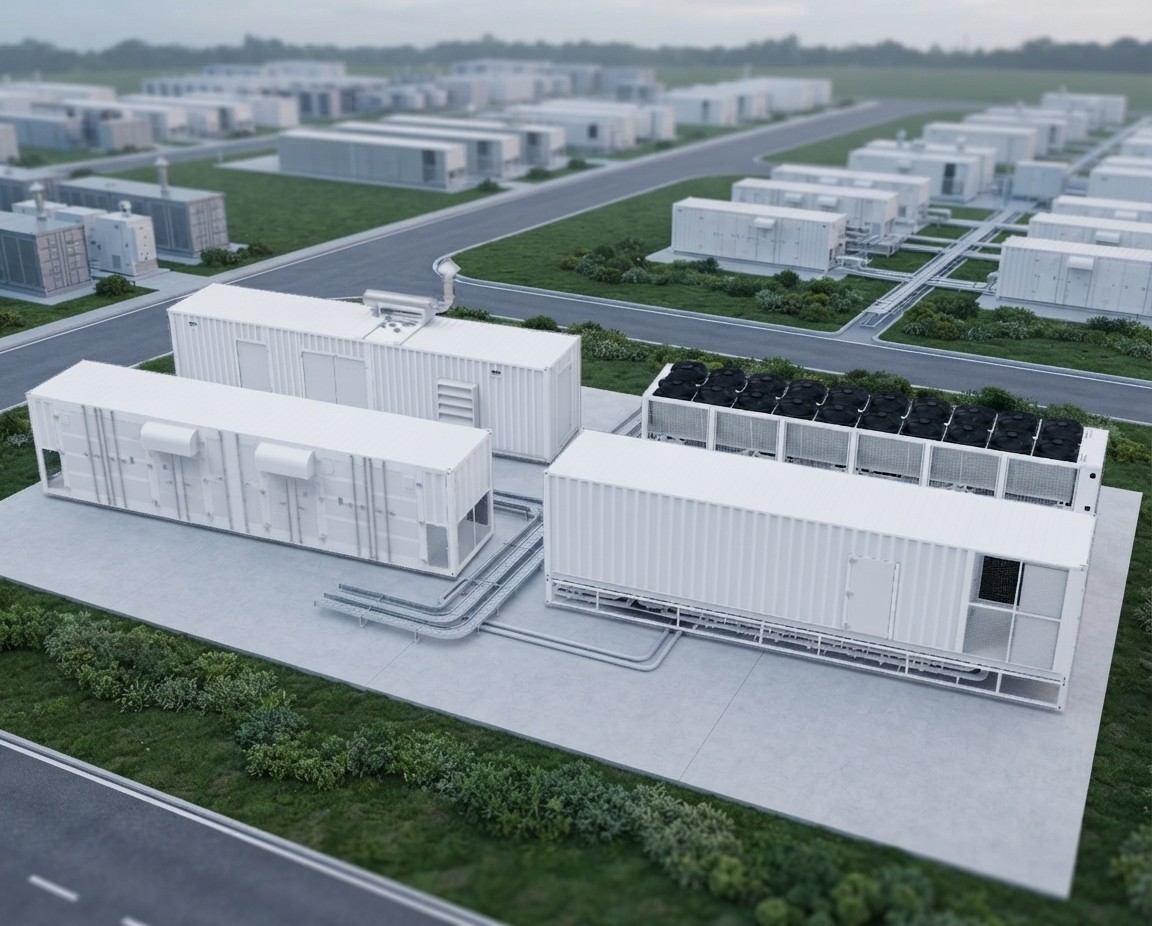
Illustrative data hall. In a distributed design CDUs sit within or between these rows; in a centralized design they sit in a separate mechanical area.
Centralized vs. distributed CDU architecture at a glance
| Factor | Centralized (facility-level) | Distributed (rack or row) |
|---|---|---|
| Failure domain | Large unless split into redundant modules | One rack or one row per unit |
| Redundancy approach | N+1 units and pumps, redundant headers and valves | Spare units, row-to-row backup, or N+1 within each unit |
| White-space use | Frees white space; needs mechanical room | Uses rack positions or row space |
| Piping | Long, larger-diameter secondary mains | Primary water routed into the hall; shorter secondary loops |
| Capacity growth | Mains sized for final build or added in phases | Added with racks, in small steps |
| Coolant management | Treatment and filtration in one place | Many smaller pumps, filters and sensors |
| Controls | Coordinated load balancing | Needs a supervisory layer to coordinate units |
| Retrofit fit | Harder in occupied halls | Usually easier |
The sections below explain why each row looks the way it does.
Failure domain and redundancy
The failure domain is the amount of IT load that goes down when one CDU stops. A rack-level unit puts one rack at risk. A row unit puts a row at risk. A single large central unit with no redundancy can put the whole hall at risk, which is why central plants are built from several CDUs with N+1 pumps and valves arranged so any unit can be isolated for service.
A small failure domain does not automatically mean small business impact. In tightly coupled AI training clusters, losing one rack can interrupt a job that spans many racks. Decide what the real blast radius is for your workload, then choose the architecture and redundancy level to match.
Whichever route you take, treat redundancy as something to prove rather than assume. Include controlled failure tests (pump trip, valve closure, loss of one primary feed) in commissioning so the sequence of operations is verified before IT load arrives.
Piping, pumping and where the coolant travels
Architecture changes which fluid runs where. In a centralized plant the treated secondary coolant travels from the mechanical area to the racks, so mains are longer and larger, pressure drop is higher and the loop needs careful hydraulic balancing. In a distributed layout, facility water is extended into the white space to reach each CDU, which means more branch connections, isolation valves and primary-side piping near the IT equipment.
Neither layout removes liquid from the hall, so leak detection, isolation valves and containment belong in both designs. A well-built pipeline network with pressure-tested joints, sensible valve zoning and sensors at low points matters more than the topology label.
Key point: pumping energy and pipe sizing follow the distance and flow you commit to on day one. Ask each vendor to show pressure-drop calculations for your actual routing, not a generic example.
Planning a liquid-cooled hall and unsure which layout fits? Talk to a liquid cooling engineer about your capacity plan and site constraints.
Scalability and phasing
Distributed CDUs grow with the racks. You buy and commission cooling capacity in small increments, which limits stranded investment when deployment schedules are uncertain. The trade-off is repetition: every added unit brings another set of connections to install, test and monitor.
Centralized plants favor builds where the final capacity is known. The risk is stranded capacity: if mains and plant space are sized for full build but IT arrives slowly, you carry cost for capacity you are not using. Phased central plants, where CDU groups are added block by block, reduce that exposure.
Prefabricated and modular designs ease either path because the CDU, pumps, valves and piping can be integrated and tested before shipment. See our overview of modular data centers for AI deployment for how that fits into site planning.
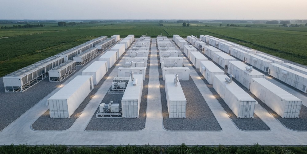
Illustrative modular site. Block-based cooling lets capacity grow one module or hall at a time.
Operations, monitoring and maintenance
A distributed fleet means more pumps, filters, sensors and firmware versions to track. Each unit is simple, but the O&M workload scales with the count, so consistent spare parts, standard service intervals and remote monitoring become essential. A centralized plant has fewer components in total, but each one carries more load and needs specialist attention, plus a team comfortable with plant-level controls and water treatment.
In both cases, check that the control system exposes the data your team needs: supply and return temperatures, flow, differential pressure, pump status, filter condition and alarms, in a form your building management system can read.
The block-based middle path
Many multi-hall and modular projects avoid the extremes. A block-based design assigns a redundant CDU group to each hall, module or build phase. The failure domain is bounded by the block, the unit count stays manageable, piping runs are short, and the block can be repeated as the campus grows. It also fits prefabricated delivery, where the cooling skid is built and tested as part of the module.
A practical decision framework
- Lean distributed when you are retrofitting an occupied hall, deployment timing is uncertain, rack densities or fluid temperatures vary, or mechanical space is limited.
- Lean centralized when you are building a large greenfield hall with a known final capacity, want one place for coolant treatment and coordinated controls, and have mechanical space and an experienced O&M team.
- Lean block-based when you are planning a modular campus or multi-phase build and want a bounded failure domain without multiplying small units.
Questions to settle before you commit
- What is the final capacity, and how will it be phased?
- What facility water class does the IT equipment require? ASHRAE's thermal guidelines define liquid cooling classes by facility water temperature, and the fifth edition requires full, unthrottled operation within the class, so start from the equipment rather than the topology.[3]
- How many racks can you afford to lose to one failure, given how jobs are scheduled?
- How will redundancy be tested during commissioning?
- Where are the isolation valves, leak sensors and drain points, and who responds to an alarm?
- What pressure drop and pump head does your actual piping route imply?
- How does the CDU layer interface with heat rejection, such as dry coolers, and with the building controls?
Related reading: direct-to-chip cooling: a technical guide and AI data center site selection.
Conclusion
Centralized and distributed CDU architecture are two ways of trading failure domain, complexity and flexibility. Small units isolate faults and grow easily but multiply the things to maintain. Central plants consolidate control and treatment but demand upfront planning and strong redundancy. Matching the architecture to your phasing plan, workload and operations capability matters more than picking the fashionable option.
Cool Space designs CDUs, dry coolers, piping networks and monitoring as one system tailored to each project, so the layout can follow your capacity plan rather than a fixed catalog configuration. Our CoolBase prefabricated modular infrastructure shows how factory-integrated liquid cooling is packaged, and our engineers can discuss your project through the project consultation page.
References
- Vertiv: Evaluating CDU architectures, advantages, considerations and best use cases
- Open Compute Project: Coolant Distribution Unit (CDU) listings
- Upsite Technologies: Major changes to ASHRAE's fifth edition of Thermal Guidelines, part 3 (liquid cooling chapter)
Frequently asked questions
What is the difference between a centralized and a distributed CDU?
A centralized CDU plant sits in a mechanical area and serves many racks through a distribution network. Distributed CDUs sit at the rack or row and each serves a small local loop.
Is a distributed CDU design more reliable?
Not by default. Distributed units shrink the failure domain of any one unit, but they increase the number of pumps, filters and sensors to maintain. Reliability depends on redundancy design, maintenance practice and commissioning failure tests.
Can a data center use both architectures?
Yes. A common pattern is a central or block-based baseline with rack or row CDUs for retrofit zones or isolated high-density areas. The units need compatible coolant chemistry and a coordinated control and monitoring layer.
Which architecture suits a modular or prefabricated data center?
Block-based layouts often fit well, with a redundant CDU group per module that is integrated and tested before shipment. The right configuration still depends on project capacity, climate and heat-rejection design.